The Working Principle of The Switch
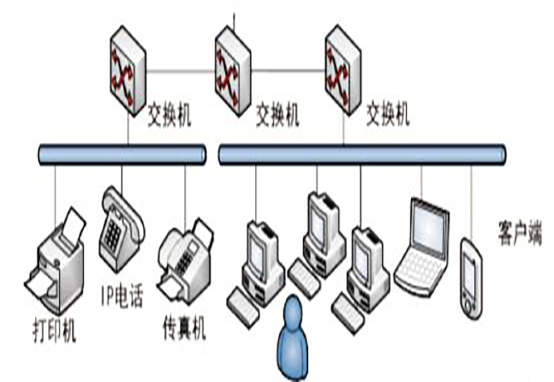
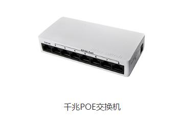
or the OSI reference model, the switch works on the second layer of this model, the data link layer. As shown in the following figure, the switch has eight ports. When a device is plugged into the switch through RJ45, the switch’s master chip will identify the ports plugged into the network cable, and the connection is successful. The mac address of the connected device is one-to-one corresponding to the port. When all eight ports are plugged in, the internal master can form a MAC table with all ports. In the subsequent port communication, when the device transmits information, it will output a data packet with a source mac and a target mac. After the data packet reaches the master control, it can quickly send the data packet to the device with the corresponding mac address through the established mac table, so as to achieve communication between devices. In addition, packets sent to the MAC address will only be sent to their corresponding ports, not all ports. Therefore, the switch can be used to divide the data link layer broadcast, that is, the conflict domain, but it can not divide the network layer broadcast, that is, the broadcast domain.
The switch has a high-bandwidth back bus and an internal switching matrix. All ports of the switch are attached to this back bus. After the control circuit receives the data packet, the processing port will look up the address comparison table in the memory to determine which port the NIC (network card) of the destination MAC (hardware address of the network card) is attached to. The data packet will be quickly transmitted to the destination port through the internal exchange matrix. If the destination MAC does not exist, it will be broadcast to all ports, After receiving the port response, the exchange will “learn” the new MAC address and add it to the internal MAC address table. The switch can also “segment” the network. The switch only allows necessary network traffic to pass through the switch by comparing it to the IP address table. Through the switch’s filtering and forwarding, the conflict domain can be cut down to a manageable size.
The above is the explanation of the working principle of the switch provided by Shenzhen HDV Phoelectron Technology Co., Ltd. hope this article can help you to increase your knowledge. Besides this article if you’re looking for a good optical fiber communication equipment manufacturer company you may consider about us.

