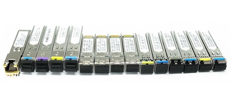
Two important considerations for using optical modules
Note that the following two points can help you reduce the loss of the optical module and improve the performance of the optical module.
Note 1:
- There are CMOS devices in this chip, so pay attention to prevent static electricity during transportation and use.
- The device should be grounded well to reduce parasitic inductance.
- Try to solder by hand, if you need machine stickers, control reflow temperature can not exceed 205 degrees Celsius.
- Do not lay copper under the optical module to prevent impedance changes.
- The antenna should be kept away from other circuits to prevent the radiation efficiency from becoming low or affect the normal use of other circuits.
- Module placement should be as far away as possible from other low frequency circuits, digital circuits.
- It is recommended to use magnetic beads for isolation of the module’s power supply.
Note 2:
- You cannot directly look at the optical module (whether long-distance or short-range optical module) that has been plugged into the device to avoid eye burns.
- With a long-distance optical module, the transmitted optical power is generally greater than the overload optical power. Therefore, it is necessary to pay attention to the length of the optical fiber to ensure that the actual received optical power is less than the overload optical power. If the length of the optical fiber is short, you need to use the long-distance optical module to cooperate with the optical attenuation. Be careful not to burn the optical module.
- In order to better protect the cleaning of the optical module, it is recommended to plug the dust plug when not in use. If the optical contacts are not clean, it may affect the signal quality and may cause link problems and bit errors.
- The optical module is generally marked with Rx/Tx, or an arrow in and out to facilitate identification of the transceiver. The Tx at one end must be connected to the Rx at the other end, otherwise the two ends cannot be linked.
